| Author | Topic |
|---|

Location:
Brisbane
Registered:
October 2004
|
|
|
Location:
PNG
Registered:
June 2002
|
|
Re: 1GGTE wiring diagrams, and other bits
|
 Thu, 07 July 2005 03:10
 
|
 |
Gidday
There may be an obvious answer - but why would you work from wire colours? Toyota does not necessarily stick to wire colours for the looms and there would be heaps of variations. Hopefully the plugs are still on the end of the loom and this is what you should be working from. The pinouts in the Tech Docs covers both gen1/2 and gen 3. Use that. If no plugs you are in strife!
Craig
|
|
|
Location:
Brisbane
Registered:
October 2004
|
|
Re: 1GGTE wiring diagrams, and other bits
|
Thu, 07 July 2005 03:11
|
|
|
i got all the plugs where they should be, i think, but that was another issue... only a handful of my plugs are listed on that toymods file...
|
|
|
Location:
Adelaide, SA
Registered:
May 2002
|
|
Re: 1GGTE wiring diagrams, and other bits
|
Thu, 07 July 2005 14:35
|
|
It aint hard to wire up a 1G... earths, constant power, switched power... might also wanna worry about the circuit open relay etc 
Anyway, wire colours mean nothing, except may be the ground wires... which are almost always brown with black dots.
|
|
|
Location:
PNG
Registered:
June 2002
|
|
Re: 1GGTE wiring diagrams, and other bits
|
Thu, 07 July 2005 22:26
|
|
I have not checked lately but the wiring diagram in Tech Docs (I think its 1G-GTE ECU Wiring.zip) is some 5-6 pages and the last 2 are plug pin outs which match the numbers on the actual diagrams, this is for a Gen 3 wiring loom. The pinouts in 1G-GTEU pin outs.doc are for a Gen 2.
Craig
|
|
|
Location:
townsville NQLD
Registered:
February 2004
|
|
Re: 1GGTE wiring diagrams, and other bits
|
Thu, 07 July 2005 23:27
|
|
i got a gen 3 1ggte now too so i also need to know which are the constant, switched power etc.
brett
|
|
|
Location:
Adelaide, SA
Registered:
May 2002
|
|
Re: 1GGTE wiring diagrams, and other bits
|
Fri, 08 July 2005 03:55
|
|
Pics?
There'll be one constant feed, two switched...
Does the ECU PCB have the pins labeled?
|
|
|
Location:
Brisbane
Registered:
October 2004
|
|
Re: 1GGTE wiring diagrams, and other bits
|
Fri, 08 July 2005 11:30
|
|
| ddeane wrote on Fri, 08 July 2005 08:26 |
I have not checked lately but the wiring diagram in Tech Docs (I think its 1G-GTE ECU Wiring.zip) is some 5-6 pages and the last 2 are plug pin outs which match the numbers on the actual diagrams, this is for a Gen 3 wiring loom. The pinouts in 1G-GTEU pin outs.doc are for a Gen 2.
Craig
|
yeah, got that but many of the plugs i have don't match the ones on the diagrams... i'm thinking i might just head down the wreckers, and raid a shell, get the other bits i need...
|
|
|
Location:
Pine Rivers QLD
Registered:
April 2005
|
|
Re: 1GGTE wiring diagrams, and other bits
|
Fri, 08 July 2005 12:34
|
|
hey man i am currently doing a conversion too, but gen 2. let me know what you need as i am in bris also and wrecking a z20...
But i think my bell housing brackets are going sorry.
|
|
|
Location:
Brisbane
Registered:
October 2004
|
|
Re: 1GGTE wiring diagrams, and other bits
|
Fri, 08 July 2005 12:37
|
|
how different is the wiring? i imagine it'd be a whole lot different, i need a bunch of bits, not sure atm what... and that's half the problem... i know i need a fuse box,igniter, and a few relays, opening circuit etc...
got all that stuff?
|
|
|
Location:
Pine Rivers QLD
Registered:
April 2005
|
|
Re: 1GGTE wiring diagrams, and other bits
|
Sat, 09 July 2005 03:41
|
|
|
yeah i dunno. it probably is. i have some of that stuff. but yeah it prob won't help much
|
|
|
Location:
townsville NQLD
Registered:
February 2004
|
|
Re: 1GGTE wiring diagrams, and other bits
|
Sat, 09 July 2005 07:04
|
|
pop the cap of the ECU and you will be able to find the pinouts that way. hydra suggested it to me and i think it be the best way to work things out.
brett
|
|
|
Location:
Adelaide, SA
Registered:
May 2002
|
|
Re: 1GGTE wiring diagrams, and other bits
|
Sat, 09 July 2005 07:06
|
|
|
note, gen2 ecu's dont seem to have the pinout written on the pcb... bit of a pain if you dont look at the repository.
|
|
|
Location:
townsville NQLD
Registered:
February 2004
|
|
Re: 1GGTE wiring diagrams, and other bits
|
Sat, 09 July 2005 07:12
|
|
|
ill get a pic up soon of my ecu board with all the pinouts so someone call tell me what i need to run it - minimum wires
|
|
|
Location:
Brisbane
Registered:
October 2004
|
|
Re: 1GGTE wiring diagrams, and other bits
|
Sat, 09 July 2005 07:25
|
|
| brett_celicacoupe wrote on Sat, 09 July 2005 17:04 |
pop the cap of the ECU and you will be able to find the pinouts that way. hydra suggested it to me and i think it be the best way to work things out.
brett
|
WHA?! the pin out is written inside the lid of the ECU? is that what you mean? 'cause that's what i understand.... hehehehe... i'm gonna go check that out... too F***en easy if that's the case
|
|
|
Location:
Adelaide, SA
Registered:
May 2002
|
|
Re: 1GGTE wiring diagrams, and other bits
|
Sat, 09 July 2005 07:45
|
|
It's on the PCB itself, not the lid.
I hope you have good eyesight though  and don't go poking things. and don't go poking things.
|
|
|
Location:
Brisbane
Registered:
October 2004
|
|
|
Location:
townsville NQLD
Registered:
February 2004
|
|
Re: 1GGTE wiring diagrams, and other bits
|
Sun, 10 July 2005 00:30
|
|
under the lid, on the PCB board is little abrreviations of what the wires are for.
example - STA (start), IGSW (ignition switch) etc.
|
|
|
Location:
Brisbane
Registered:
October 2004
|
|
Re: 1GGTE wiring diagrams, and other bits
|
Sun, 10 July 2005 08:21
|
|
hmmm... fair enough... still not what i'm looking for, but it'll probably help me if i can't figure out a way... i think there's a list of the same under the articles section... under "1GGTEU ecu pinouts"
cheers
|
|
|
Location:
townsville NQLD
Registered:
February 2004
|
|
|
Location:
Brisbane
Registered:
October 2004
|
|
Re: 1GGTE wiring diagrams, and other bits
|
Mon, 11 July 2005 12:48
|
|
|
download the file under the articles section on the home page named "1ggteu pin outs" i think that'll be the one you want
|
|
|
I supported Toymods
Location:
Australia
Registered:
November 2003
|
|
Re: 1GGTE wiring diagrams, and other bits
|
Tue, 12 July 2005 05:02
|
|
SP1 is speed sensor 1 input
SP2 is speed sensor 2 input
FPR is Fuel Pump Relay
W is Check Engine Light
M-REL is Main Relay
NSW is Neutral Switch
P is the Auto Power Switch (Power/ECON)
B is +12v IGN
+B1 is +12v IGN
ACxx is usually AirCon related
Thats all I know sorry.
|
|
|
I supported Toymods
Location:
Australia
Registered:
November 2003
|
|
Re: 1GGTE wiring diagrams, and other bits
|
Tue, 12 July 2005 05:13
|
|
L1, L2, L3, and ECT are all AutoECU related.
As for EGW, TILL, CCO, M, I am not sure.
CCO sounds like it could be the VSV output for the Charcoal Canister.
EGW may be something EGR related at a guess??
TILL could be Turbo Indicator Light or something??
M has me stumped though.
Check the other 2 plugs, then we can rule out what it CANT be.
|
|
|
Location:
townsville NQLD
Registered:
February 2004
|
|
Re: 1GGTE wiring diagrams, and other bits
|
Tue, 12 July 2005 10:49
|
|
thanks for that cruzida
but would you be able to tell me which ones i need connected as a minimum for the engine to run??
thanks again
brett
|
|
|
I supported Toymods
Location:
Australia
Registered:
November 2003
|
|
Re: 1GGTE wiring diagrams, and other bits
|
Tue, 12 July 2005 12:39
|
|
Can you get the pins for the other 2 plugs?
Is it gen 1, 2 or 3?
|
|
|
I supported Toymods
Location:
Australia
Registered:
November 2003
|
|
|
Location:
townsville NQLD
Registered:
February 2004
|
|
Re: 1GGTE wiring diagrams, and other bits
|
Wed, 13 July 2005 03:46
|
|
yeh ive got all the 1g stuff out of the tech docs but what i want to know is if i need ALL of these connected:
| Quote: |
SP1 is speed sensor 1 input
SP2 is speed sensor 2 input
FPR is Fuel Pump Relay
W is Check Engine Light
M-REL is Main Relay
NSW is Neutral Switch
P is the Auto Power Switch (Power/ECON)
B is +12v IGN
+B1 is +12v IGN
ACxx is usually AirCon related
|
with my engine loom, it only has 2 of the 3 ecu plugs hardwired to this loom.
the third ECU plug (22pin'er - the one i am inquiring about) i expect was hardwired to the loom under the dash - ie. seperate to the engine loom
so do i need ALL of those pins connected??? bar the auto box crap (i got manuual)
thanks
|
|
|
I supported Toymods
Location:
Australia
Registered:
November 2003
|
|
Re: 1GGTE wiring diagrams, and other bits
|
Wed, 13 July 2005 03:58
|
|
FPR will be needed to turn the fuel pump on.
M-REL will need to be connected
B and +B1 will need to be connected.
BATT and IGSW will need to be connected.
STA will need to be connected.
SP1 will be touch and go. It might work without it, it might go into limphome.
|
|
|
Location:
townsville NQLD
Registered:
February 2004
|
|
Re: 1GGTE wiring diagrams, and other bits
|
Wed, 13 July 2005 04:19
|
|
thanks
that was exactly what i was after
with the sp1, this would normally get a signal from the speedo rite??-im guessing
thanks again for your help
wtf does limphome mean?? 
|
|
|

Location:
Brisbane
Registered:
April 2003
|
|
Re: 1GGTE wiring diagrams, and other bits
|
Wed, 13 July 2005 04:27
|
|
Limp home mode... means the computer will retard timing and possibly richen the mixture so you don't do any damage to the engine. Suffice to say the car won't be moving anywhere fast 
|
|
|
Location:
townsville NQLD
Registered:
February 2004
|
|
Re: 1GGTE wiring diagrams, and other bits
|
Wed, 13 July 2005 04:29
|
|
haha 
sounds like you are speaking from experience 
|
|
|
Location:
townsville NQLD
Registered:
February 2004
|
|
Re: 1GGTE wiring diagrams, and other bits
|
Wed, 13 July 2005 04:30
|
|
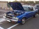
BTW: had a look at your car
very impressive 
nice colour too
|
|
|
I supported Toymods
Location:
Australia
Registered:
November 2003
|
|
Re: 1GGTE wiring diagrams, and other bits
|
Wed, 13 July 2005 04:31
|
|
Yes, SP1 is the 4 pulse per rev output from the back of the speedo.
I'm not sure if RA40's have it, but I know everything from RA60 on does.
|
|
|
Location:
Brisbane
Registered:
April 2003
|
|
Re: 1GGTE wiring diagrams, and other bits
|
Wed, 13 July 2005 04:42
|
|
| brett_celicacoupe wrote on Wed, 13 July 2005 14:30 |
sounds like you are speaking from experience
BTW: had a look at your car
very impressive
nice colour too
|
Yeah, I've had mine in Limp Home Mode before... not much fun I can tell you...
Thanks for the comments... she's still very much a work in progress though
Cheers,
Kirk
|
|
|
Location:
Brisbane
Registered:
October 2004
|
|
Re: 1GGTE wiring diagrams, and other bits
|
Thu, 14 July 2005 01:45
|
|
| CrUZsida wrote on Wed, 13 July 2005 14:31 |
Yes, SP1 is the 4 pulse per rev output from the back of the speedo.
I'm not sure if RA40's have it, but I know everything from RA60 on does.
|
what about RA28's? does this mean you can just wire the sp1 to the speedo....
hang on... *thinking*
speedo has input from g'box... "4 pulse per rev output" means it has an output too!? and that goes TO the ecu via the SP1 connection/pin
|
|
|
I supported Toymods
Location:
Australia
Registered:
November 2003
|
|
Re: 1GGTE wiring diagrams, and other bits
|
Thu, 14 July 2005 01:51
|
|
| hickoz_bro wrote on Thu, 14 July 2005 09:45 |
hang on... *thinking*
speedo has input from g'box... "4 pulse per rev output" means it has an output too!? and that goes TO the ecu via the SP1 connection/pin
|
Can you expand on your thinking?
|
|
|
Location:
Brisbane
Registered:
October 2004
|
|
Re: 1GGTE wiring diagrams, and other bits
|
Thu, 14 July 2005 02:04
|
|
well this is not related on a "how to" level, moreso on a "why" level... the speedo is the bit dial that tell your speed... right... it has a mechanical input from the back of the gearbox, when you said it has a "4 pulse per rev output" does that mean the speedo sends signals to the ECU via the SP1 pin/wire,
el comprehendaé?
|
|
|
I supported Toymods
Location:
Australia
Registered:
November 2003
|
|
Re: 1GGTE wiring diagrams, and other bits
|
Thu, 14 July 2005 02:19
|
|
Yes, the SP1 input to the ecu comes from an output on the back of the speedo.
As the speedo cable turns in the back of the ecu either a 4 tooth disc passes by a hall effect/reluctance type sensor, or something physically comes incontact with the 4tooth disc.
This is definately on all RA60 and on speedo's, but I don't know about anything earlier.
|
|
|
Location:
Brisbane
Registered:
October 2004
|
|
|
I supported Toymods
Location:
Australia
Registered:
November 2003
|
|
Re: 1GGTE wiring diagrams, and other bits
|
Thu, 14 July 2005 02:30
|
|
| hickoz_bro wrote on Thu, 14 July 2005 10:23 |
when you say it's on all RA60/later models, does that mean the earlier models may not have the output? or they may have a different style/signal output?
|
Most likely don't have one, but I don't know.
| hickoz_bro wrote on Thu, 14 July 2005 10:23 |
and that list of wires you said need to be connected... is that enough to get the engine running????
|
That what was needed out of that plug.
I don't know about the other plugs.
|
|
|
Location:
Brisbane
Registered:
October 2004
|
|
Re: 1GGTE wiring diagrams, and other bits
|
Thu, 14 July 2005 05:37
|
|
can anyone recommend a throttle cable to use?
|
|
|
Location:
townsville NQLD
Registered:
February 2004
|
|
Re: 1GGTE wiring diagrams, and other bits
|
Thu, 14 July 2005 08:53
|
|
| hickoz_bro wrote on Thu, 14 July 2005 15:37 |
can anyone recommend a throttle cable to use?
|
MX62 cressida cable is what i have on mine. i got the whole cable/pedal setup and ovaled out the holes for the pedal pivot and bolted it to where the old RA40 one went. i then put a couple screws through the flange looking thing into the firewall.
bit of tweaking of the pedal rod required too.
presto!!
i had this setup on the 18rg and it worked fine, although it was a little long because of the throttle being on the drivers side...so it was looped.
although it will be perfect for the 1g seeing as the car it came off (5me) had the throttle body on the passenger side - same as 1g
| CrUZsida wrote on Thu, 14 July 2005 12:30 |
| hickoz_bro wrote on Thu, 14 July 2005 10:23 |
when you say it's on all RA60/later models, does that mean the earlier models may not have the output? or they may have a different style/signal output?
|
Most likely don't have one, but I don't know.
| hickoz_bro wrote on Thu, 14 July 2005 10:23 |
and that list of wires you said need to be connected... is that enough to get the engine running????
|
That what was needed out of that plug.
I don't know about the other plugs.
|
other 2 ECU plugs are a stright plug in for me
|
|
|
Location:
Pine Rivers QLD
Registered:
April 2005
|
|
Re: 1GGTE wiring diagrams, and other bits
|
Mon, 18 July 2005 12:17
|
|
|
yeah but thats the same sort of trouble i am having. just because it plugs in doesn't mean it will run sweet. some of those wire could easily be a straight run to another unplugged plug somewhere, as you have more then just two ECU plugs on that loom no?
|
|
|


